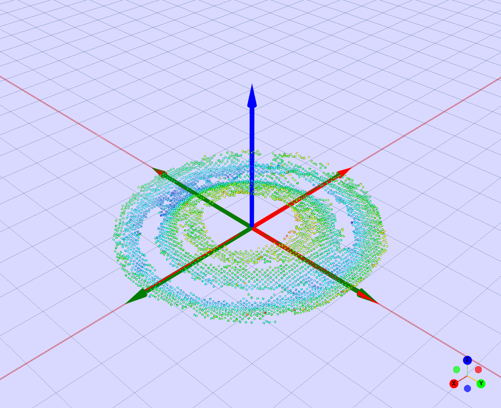
Pick Points
The Pick Points Editor allows you to create and edit pick points for the 3D models generated for your objects. A pick point defines a pose (position X/Y/Z in mm + orientation rX/rY/rZ in degrees) that Pick[+] uses as a grasp candidate.
Best practices
- If the application allows it, it's recommended to define multiple pick points per object to ensure at least one feasible grasp is available despite occlusions
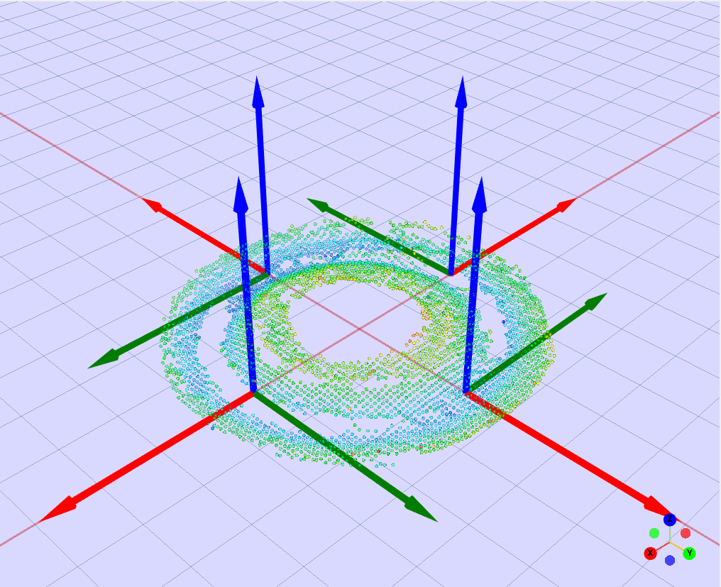
- For circular parts (washers, caps, cylinders), use revolution points to create evenly-spaced grasps around a circumference
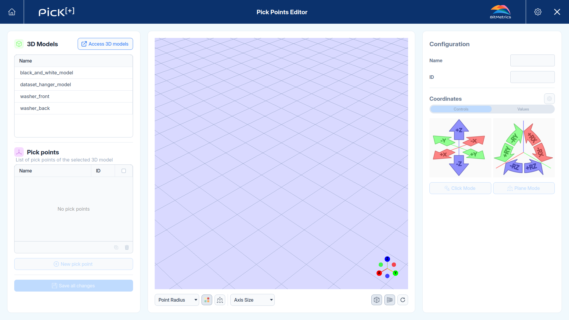
The interface is divided into three main areas:
| Panel | Contents |
|---|---|
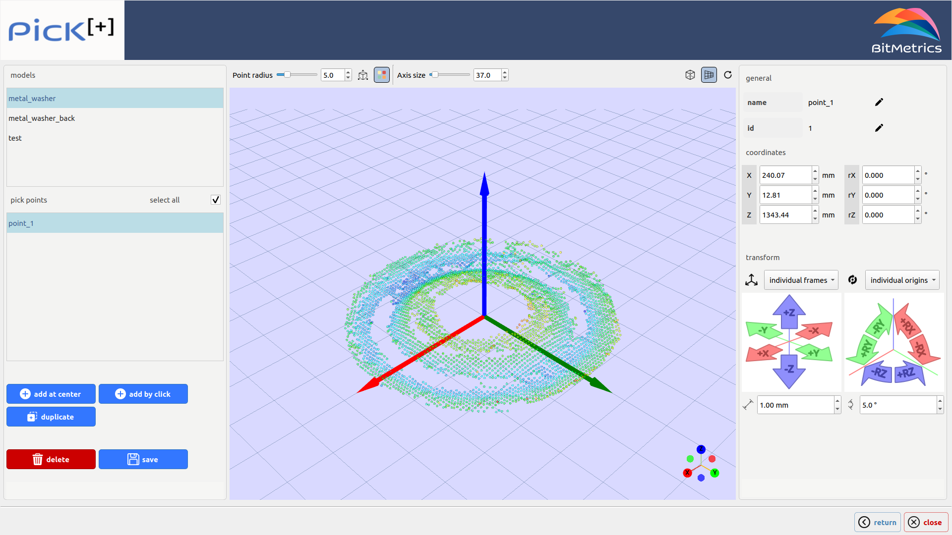
| Left | Model list and pick points list with action buttons |
| Center | 3D viewer displaying the model point cloud and pick points |
| Right | Properties panel for the selected pick point: name, ID, coordinates, and transform controls |
Viewer Toolbar

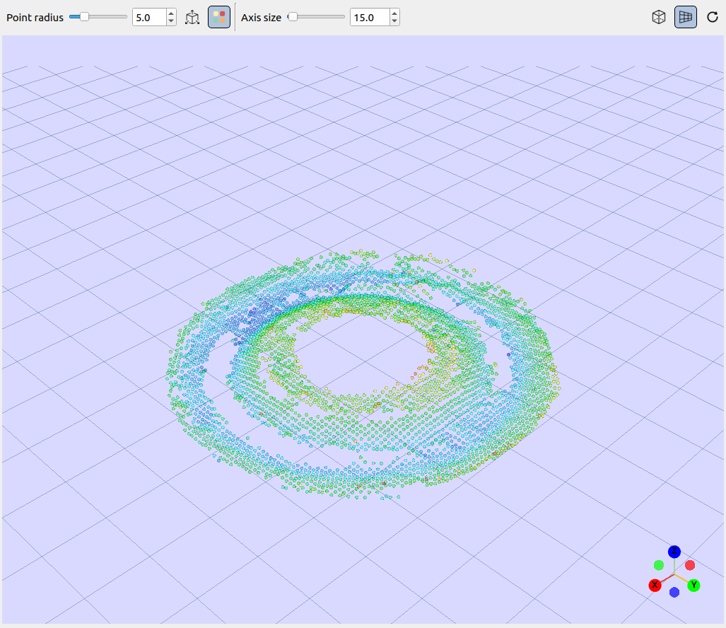
The toolbar at the bottom controls visualization settings only, it does not modify the model or its pick points. Select a setting to see what it does.
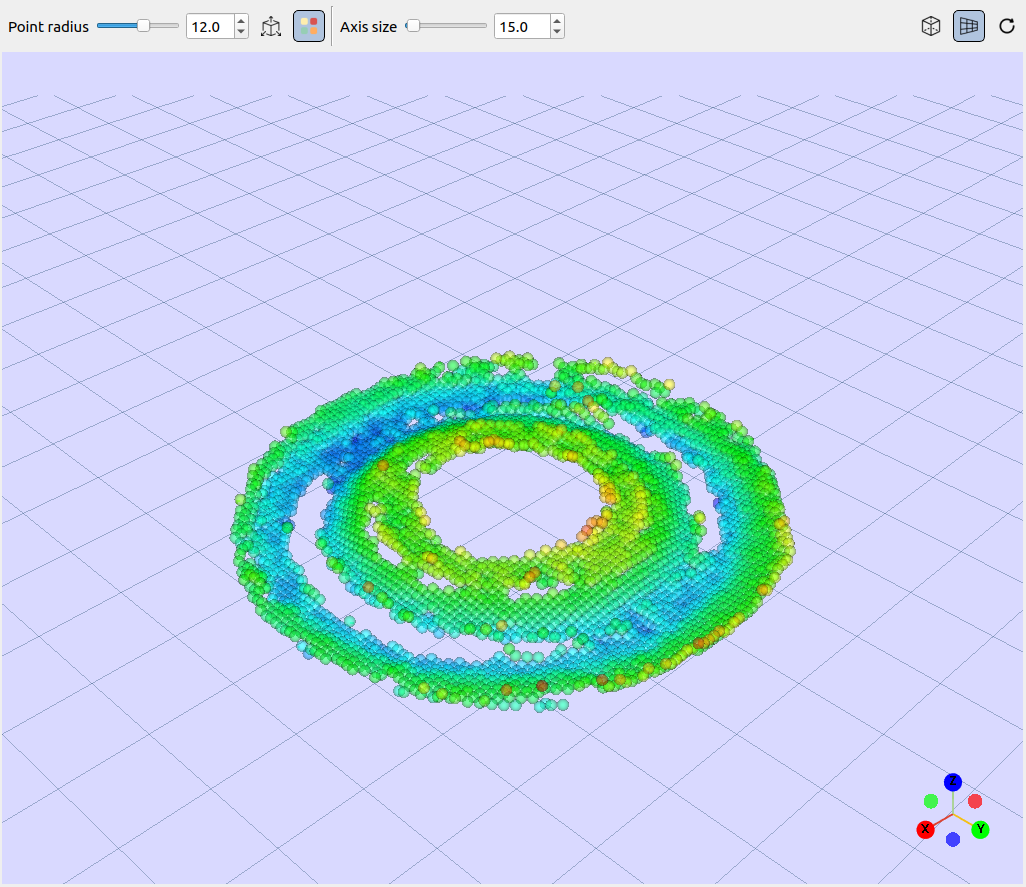
Point Radius
Adjusts the visual size of the point cloud dots. Useful for fine-tuning visibility on sparse or dense clouds.
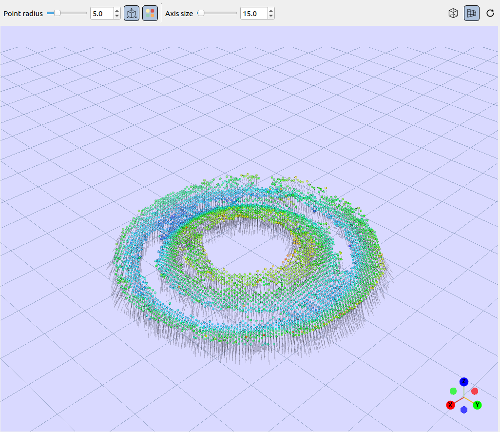
Normals
Toggles visibility of surface normals (lines perpendicular to each surface point). Useful for verifying surface orientation.
Color
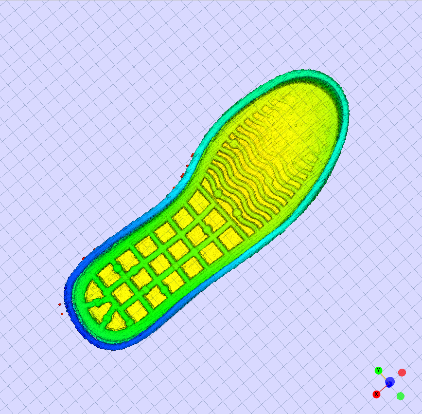
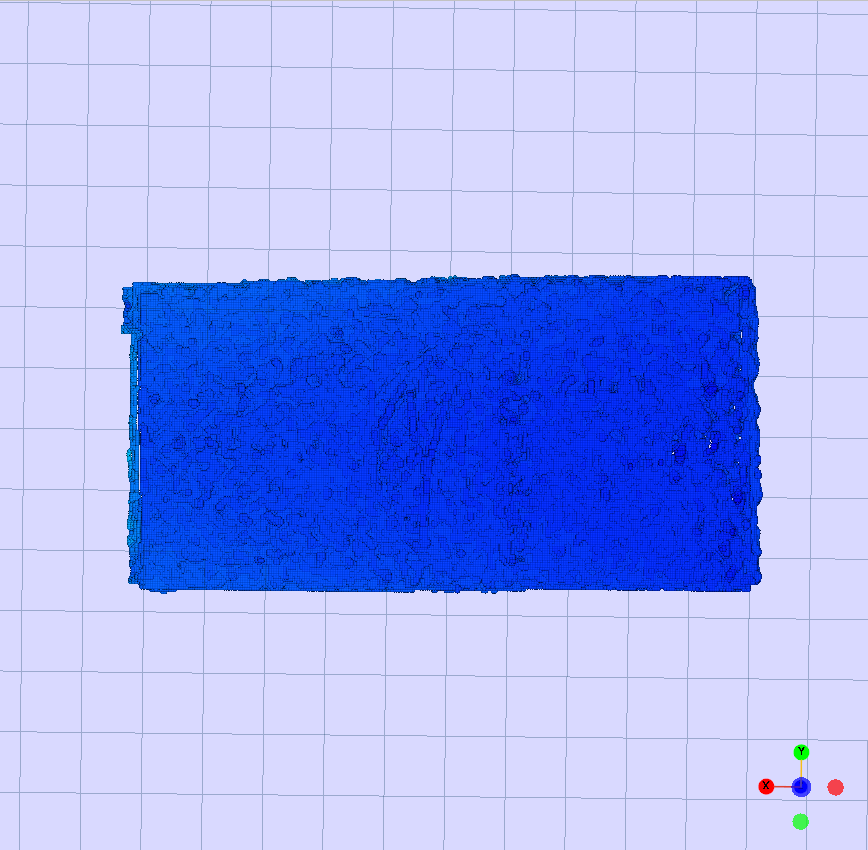
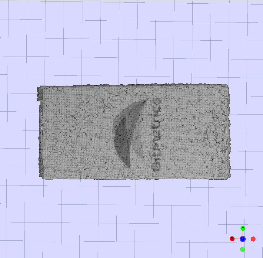
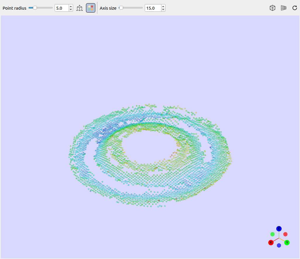
Switches between color modes for the point cloud: distance-based color mode vs texture mode. Distance color helps read the geometry of complex shapes, while texture mode reveals the real surface detail. If the point cloud is all black, there is no texture available for that 3D model.
Complex geometry: distance color highlights the relief and depth.
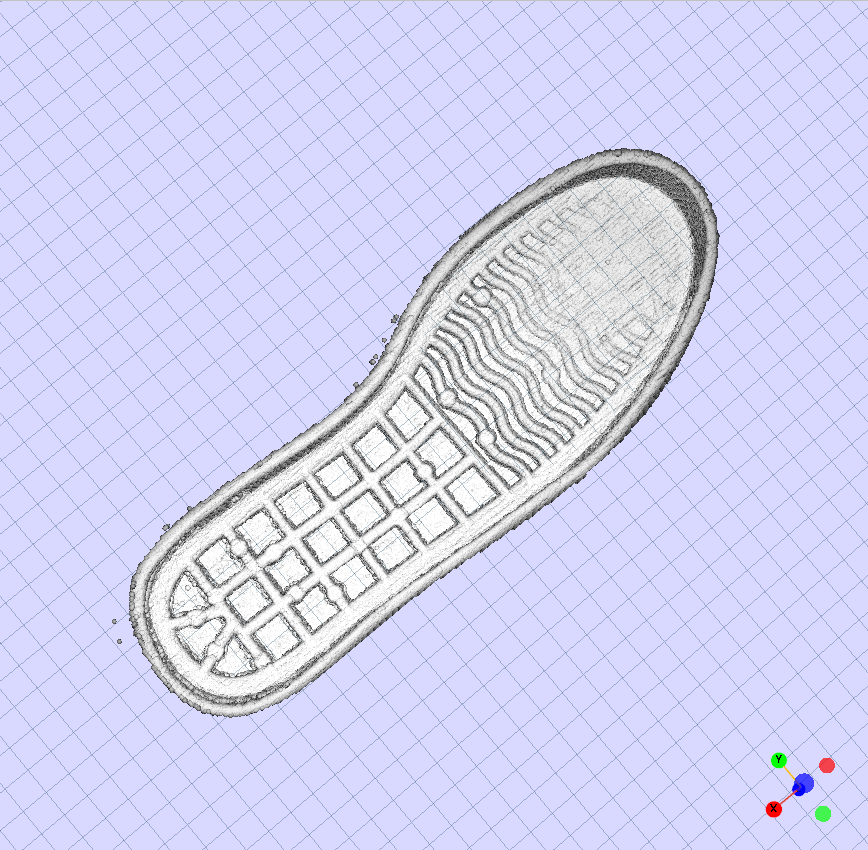
Flat part: texture mode shows the printed surface detail.
Perspective
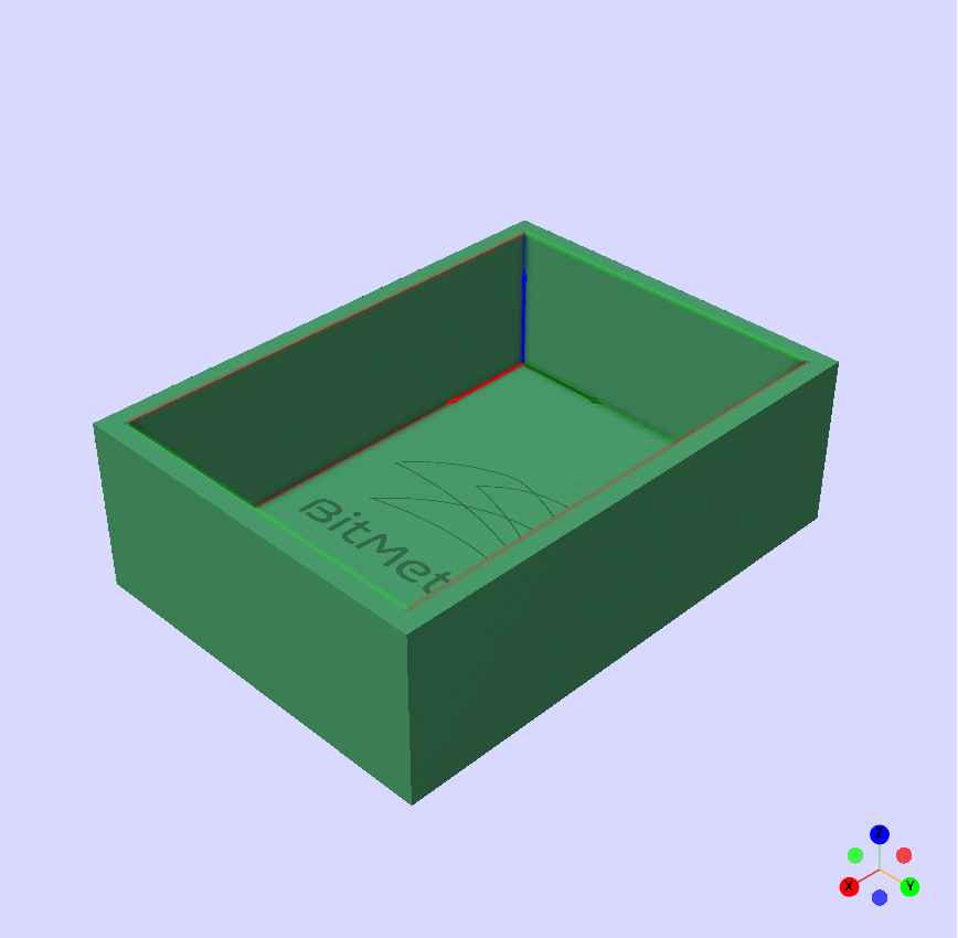
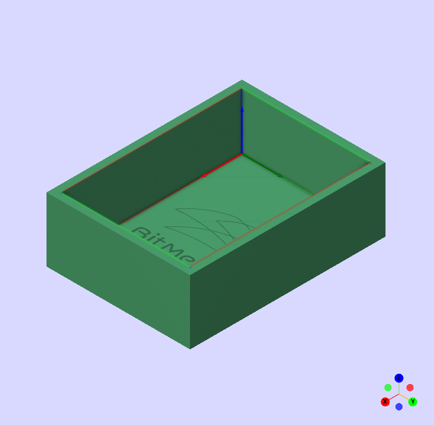
Toggles between perspective and orthographic projection. Orthographic is useful for precise editing without visual distortion.
Grid
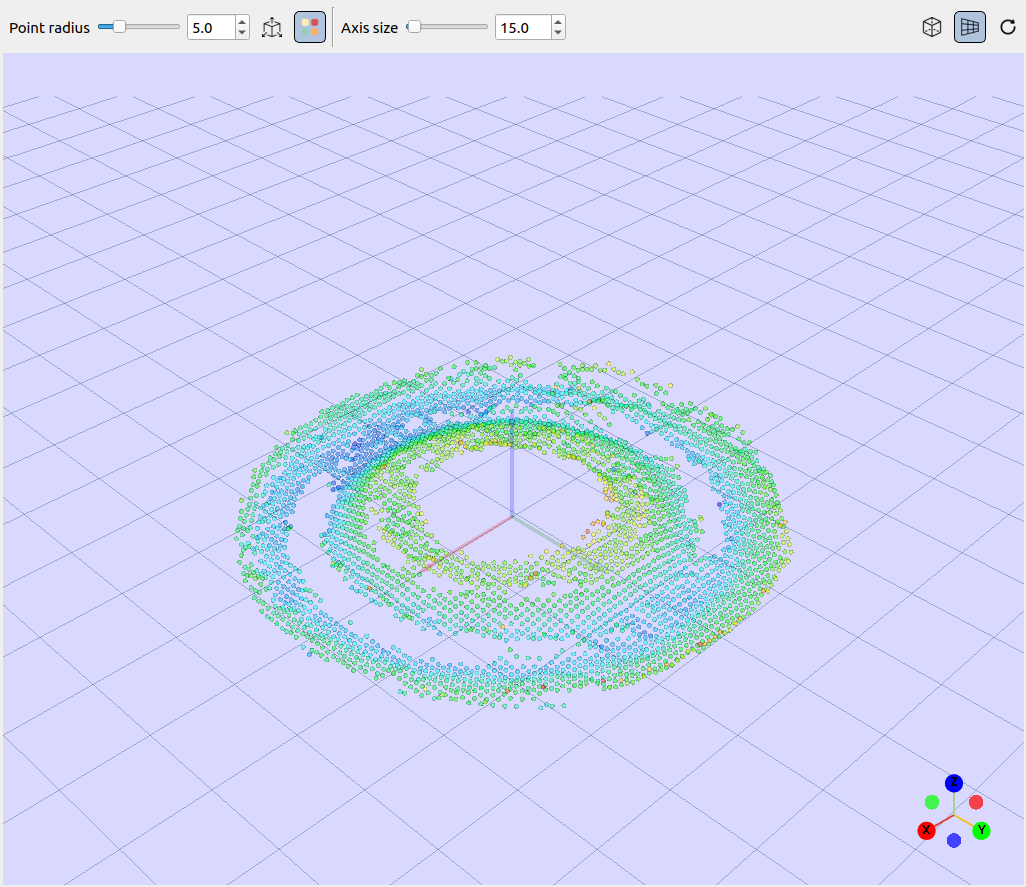
Shows or hides the reference plane grid.
Axis Size
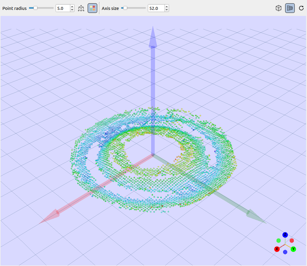
Scales the coordinate axis gizmo for better visibility.
Reset View
Resets camera position and zoom to the default state. This control has no visual setting, it simply recenters the model in the viewer.
Select a 3D Model
In the left panel under Models, select the 3D model you want to work with.
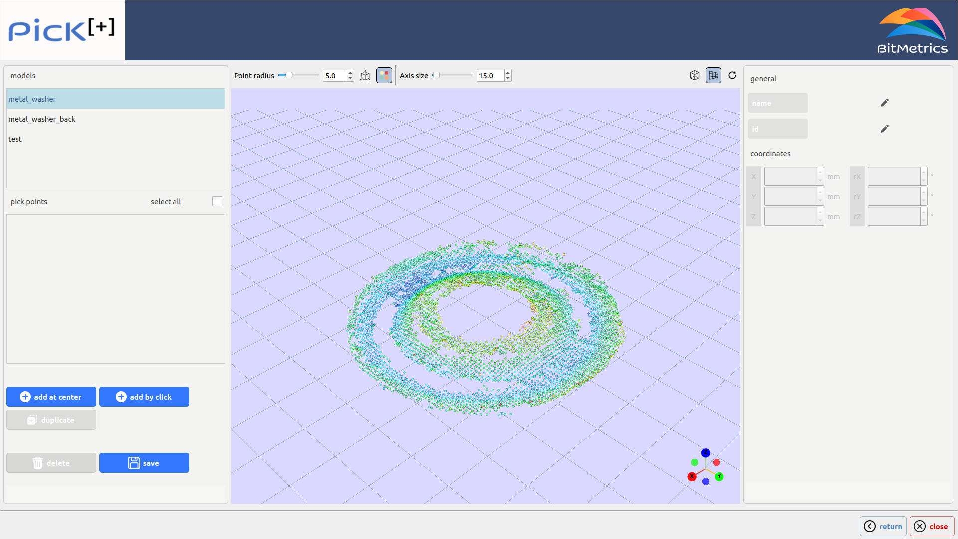
When you select a model, the 3D viewer loads its point cloud representation and the Pick Points panel displays any existing points.
Add a Pick Point
Two methods are available for creating pick points:
-
Add at Center
Creates a new pick point at the model's centroid. This is the quickest starting point.
-
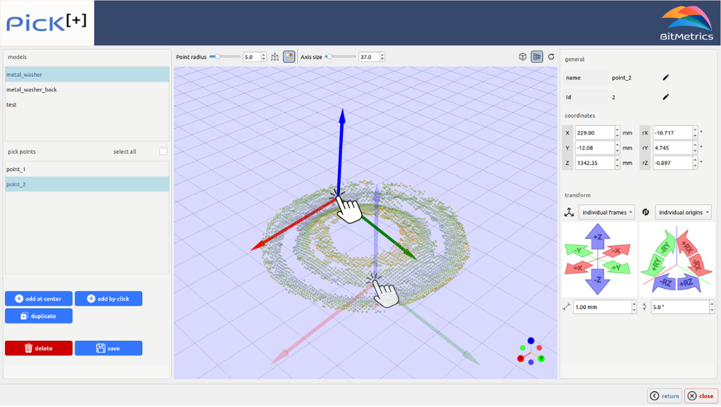
Add by Click
Creates a pick point by clicking directly on the model surface in the 3D viewer.
Modify a Pick Point
Select a point from the Pick Points list to view and edit its properties in the right panel.
Name and ID
- Name: Editable label for the point (useful for identifying grasp strategy, side, tool, etc.)
- ID: Numeric identifier for the point. After a pick, Pick[+] reports which point was selected through this ID: the
PP_PICK_IDvariable in the robot program and thePICK_IDregister in the PLC.
Coordinates
Controls
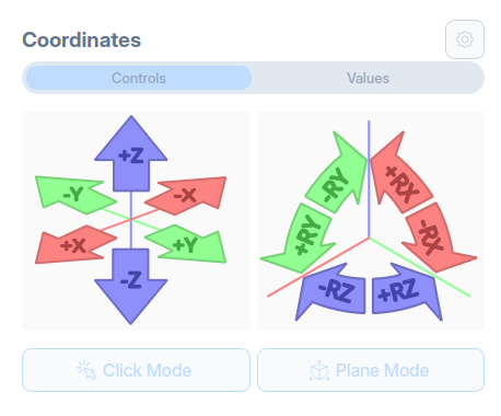
The transform widget provides precise control over pick point positioning with move and rotate controls.
-
Move Controls: The left widget handles translation along each axis: +X, -X, +Y, -Y, +Z, -Z
-
Rotate Controls: The right widget handles rotation around each axis: +rX, -rX, +rY, -rY, +rZ, -rZ
Values
Define the pick point pose using six values:
| Parameter | Unit | Description |
|---|---|---|
| X, Y, Z | mm | Position in 3D space |
| rX, rY, rZ | ° | Rotation angles |
You can edit coordinates by:
- Typing values directly in the numeric fields
- Using the Transform widget
Advanced options
Step Size, Frame Reference and Origin / Pivot are advanced transform settings. Open them with the gear icon to the right of Coordinates.
Step Size
Set the increment applied by each move and rotate control:
- Translation step: in mm (e.g., 1.00 mm)
- Rotation step: in degrees (e.g., 5.0°)
Frame Reference
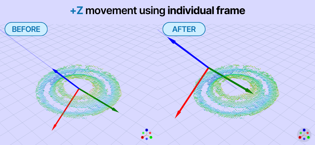
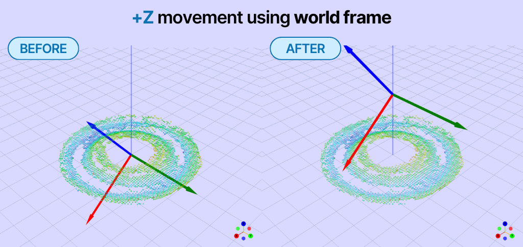
Determines which coordinate system is used for transformations:
| Frame | Behavior |
|---|---|
| Individual Frames | Uses the local axis of the pick point (respects current orientation) |
| World Frame | Uses the global scene axis |
Origin / Pivot
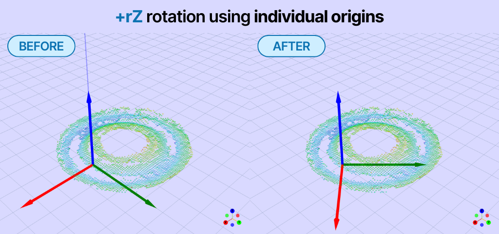
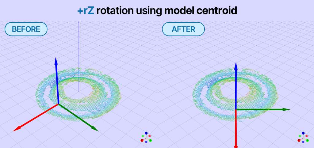
Defines the pivot point for transformations:
| Origin | Behavior |
|---|---|
| Individual Origins | The pivot is the pick point itself |
| Model Centroid | The pivot is the center of the model (useful for radial rotations around circular parts) |
Revolution Points
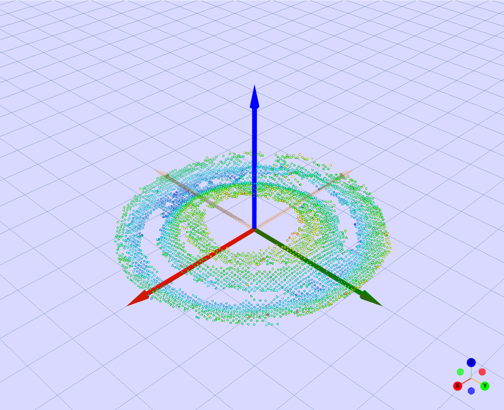
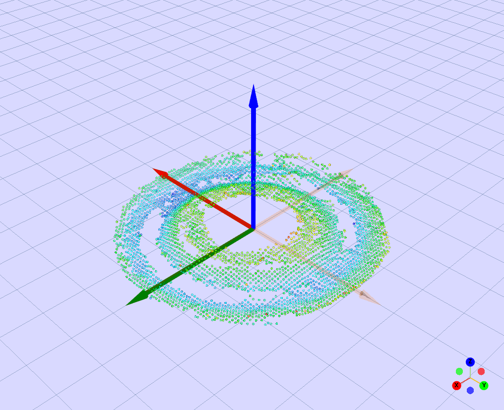
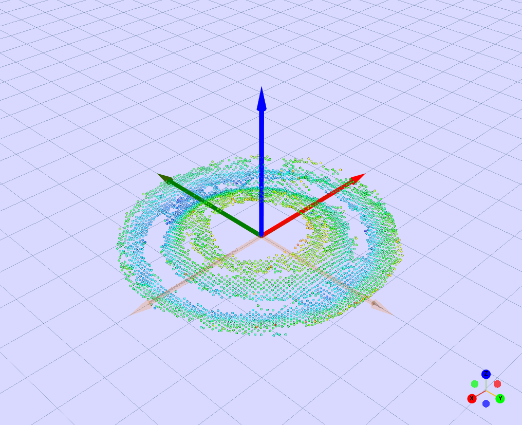
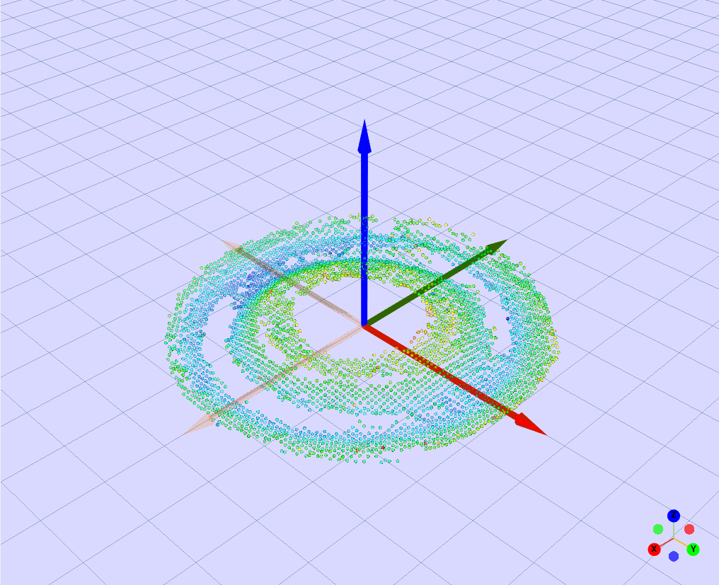
For circular parts (washers, caps, cylinders), you create evenly-spaced pick points around a circumference using this workflow:
-
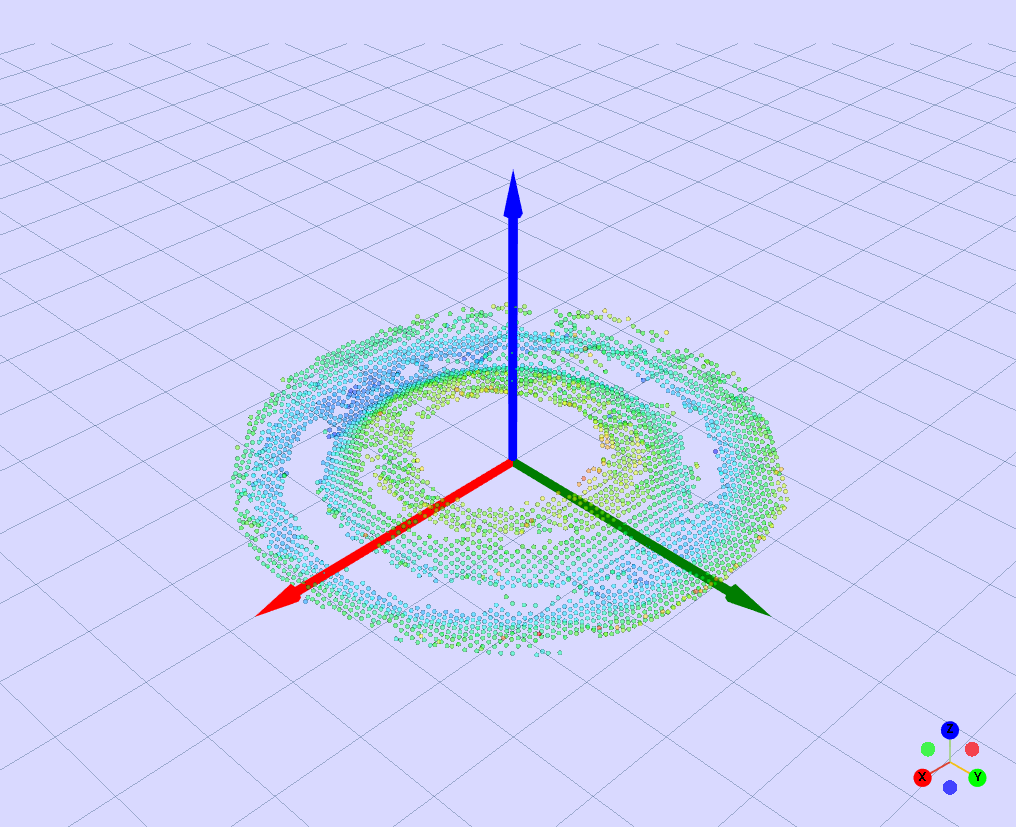
Create and adjust a point on the center of the circumference
-
Duplicate the point until you have N total points
-
For each duplicated point:
- Set Frame =
Individual framesand Origin =Individual frames - Apply rotation in using increments of x=360º/N , so each point is rotated x, 2x, 3x, etc.
- Set Frame =
-
Select all the points in the pick points list and move them (using
Individual frames)