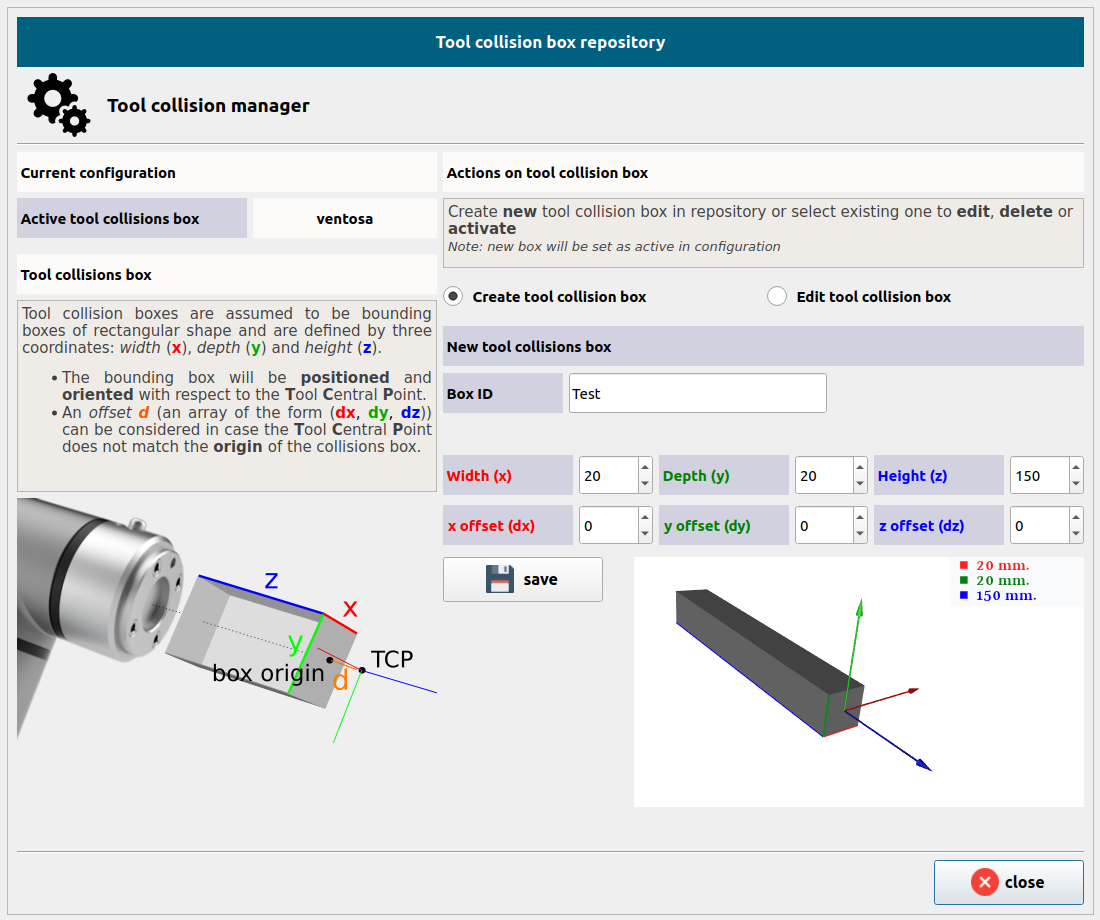
Tool Collision Manager
In order to deal with collisions related to the tool in pick trajectories you can define a 3D rectangle as the tool bounding box that will be used as the tool reference for collision assessment.
Tool collision boxes are rectangular bounding volumes defined by three dimensions:
- Width (
x) - Depth (
y) - Height (
z)
The collision box is:
- Positioned and oriented relative to the Tool Center Point (TCP).
- Optionally offset by a vector
(dx, dy, dz)if the TCP does not coincide with the box's origin.
To define / edit a new tool bounding box go to Tool/Environment Manager on the Homepage and then click Collision Box Manager
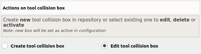
Create tool collision box
Select the option Create tool collision box under the heading Actions on tool collision box.
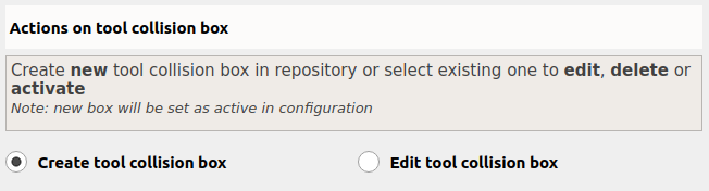
Set a Box ID and the dimensions parameters to define the new collision box.
The 3D rectangle is defined with respect to the robot TCP
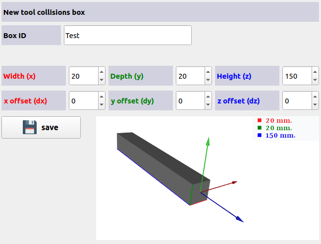
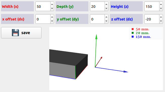
The offset needs to be a value smaller than or equal to 0 that indicates how far from the TCP we place the origin of the 3D rectangle (generally they will coincide. I.e., value 0).
Click Save to confirm and activate the collision box.
Edit collision box
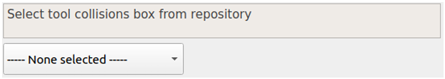
To edit existing collision box select the option Edit tool collision box under the heading Actions on tool collision box.
Select collision box from the drop-down menu:
Once finished, click Set as active and Save